
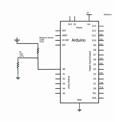
This is a schematic of the moisture sensor used throughout this project. This circuit was not only used for the moisture sensor placed in the plant directly, but also the water tank. The idea capitalizes on the fact that tap water is conductive. When two leads are placed in water, the circuit becomes complete. The resistance in the water is shown as a resistor because some current is lost in the water. We used this knowledge to determine how wet a potted plant’s soil is. In the water tank, this circuit was used to light up LEDs to show how high the water level is at any given time. Three leads were placed at intervals going up the side of the tank such that when the water sank below one of the leads, the LED would turn off.
Using the moisture sensor circuit for the tank level problem was not our first as a solution. However, once we did choose to use a similar system for the tank level sensors, there were two ways in which we could implement them. At first we tried to have the leads complete the LED circuit directly: tackle this problem with hardware. However, the water proved to be too resistive for the LEDs and caused them to shine very dimly. Instead, we solved the problem using software. The leads for the water (the moisture sensor circuit) were completely separate from the LED circuit. The microcontroller was programmed such that the sensors dictated when the LEDs were given power by the Arduino.
Using the moisture sensor circuit for the tank level problem was not our first as a solution. However, once we did choose to use a similar system for the tank level sensors, there were two ways in which we could implement them. At first we tried to have the leads complete the LED circuit directly: tackle this problem with hardware. However, the water proved to be too resistive for the LEDs and caused them to shine very dimly. Instead, we solved the problem using software. The leads for the water (the moisture sensor circuit) were completely separate from the LED circuit. The microcontroller was programmed such that the sensors dictated when the LEDs were given power by the Arduino.
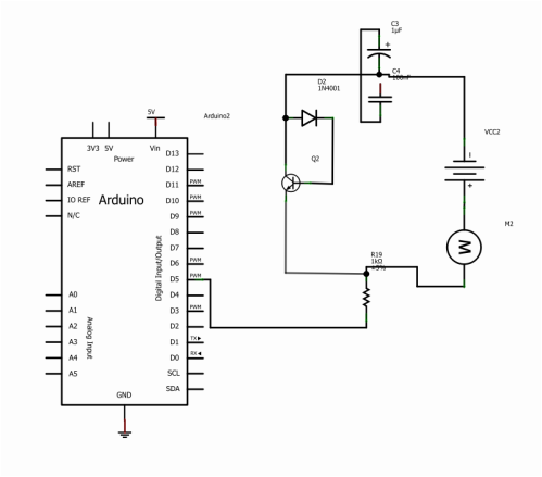
This is an example of the DC motor controller built to power the water pump. The microcontroller powers the transistor which has control over the current get to the DC motor. When the Arduino gives power to the transistor, the circuit is completed and the current is allowed to pass through to the motor. Using this we prescribed three different modes of operation so different amounts of watering could be achieved, thus allowing for different types of plants. To choose the plant type watering level, a button was added to circuit as well as LEDs which toggled to show which setting the user had chosen.
The one issue that was neglected until the final mechanical, electrical, software integration: keeping everything together. Because everyone on the team primarily had more mechanical experience than any other type of engineering, our final circuit board was not as polished or final as it could have been. The final circuit was built on a bread board meant for temporary construction. On top of this, the final housing for the project required that the electrical system be turned on its side. Each time we attempted to put all of the working parts together in this box, wires would come out and frustration levels would rise. Our simplest solution in a time crunch: find a way to semi-permanently affix the wires to the breadboard. When that was not enough, we removed the peristaltic pump from the container (so we could showcase it, of course) and allowed the electrical hardware to lay flat in the space remaining.
The one issue that was neglected until the final mechanical, electrical, software integration: keeping everything together. Because everyone on the team primarily had more mechanical experience than any other type of engineering, our final circuit board was not as polished or final as it could have been. The final circuit was built on a bread board meant for temporary construction. On top of this, the final housing for the project required that the electrical system be turned on its side. Each time we attempted to put all of the working parts together in this box, wires would come out and frustration levels would rise. Our simplest solution in a time crunch: find a way to semi-permanently affix the wires to the breadboard. When that was not enough, we removed the peristaltic pump from the container (so we could showcase it, of course) and allowed the electrical hardware to lay flat in the space remaining.
